|
|
|
|
|
|
+ نوشته شده در شنبه بیست و دوم اردیبهشت ۱۳۸۶ ساعت 18:45 توسط راشد جعفری
|
موتورهای شش زمانه
لفظ موتورهای شش زمانه به موتورهايی اطلاق می شود که ريشه ترکيبی از دو موتور، دو و چهار زمانه دارد. از محاسن اين موتور می توان به توان و گشتاور بالای آن (حدوداً 23% افزايش در مقايسه با موتورهای بنزينی چهار زمانه) اشاره نمود همچنين مصرف سوخت و آلايندگی کمتر بدليل به سوزی سوخت در اين موتور.
اين موتور دارای يک پيستون با قطر کمتر در بالای پيستون اصلی می باشد که حرکت خود را با استفاده از يک رابط (زنجير يا تسمه) از ميل لنگ می گيرد و در حين حرکت خود در راستای حرکت پيستون اصلی علاوه بر تغيير حجم موتور در کورس های مختلف (مکش، تراکم، انبساط و تخليه) کار سوپاپهای هوا و دود را نيز انجام می دهد.
اين موتور برپايه يک موتور Ducati نمونه سازی و تست شده است. از آنجاييکه اين موتور تنها نمونه سازی شده و در مرحله patent می باشد و هنوز تجاری نشده است، لذا اطلاعات زيادی در مورد نحوه عملکرد آن در دست نمی باشد.
اميدوارم که تصاوير زير در درک بهتر مطلب شما را ياری کند.
شبيه سازی يک موتور شش زمانه

نمای برش خورده موتور شش زمانه؛ دقت کنيد که هر سيلندر دارای دو شمع می باشد.
موتور شش زمانه نمونه سازی شده بر پايه موتور Ducati V-Twin
+ نوشته شده در شنبه بیست و دوم اردیبهشت ۱۳۸۶ ساعت 18:29 توسط راشد جعفری
|
This is our aim
To keep pace with the rest of the world
+ نوشته شده در شنبه پانزدهم اردیبهشت ۱۳۸۶ ساعت 11:24 توسط راشد جعفری
|
مقدمه:
آلايندگي و مصرف سوخت خودروها بدليل محدوديتهاي زيست محيطي، ظرف 10 سال آينده بايستي به ميزان قابل توجهي بهبود يابد. فن آوريهاي جديد در زمينه موتورهاي بنزيني، نظیر كوچك سازي موتورها به لحاظ اندازه (Downsizing) با استفاده از تقويت بالای آنها (High Boosted)، موتورهاي با تزريق مستقيم (GDI) و سيستم سوپاپهاي كاملاً متغير (Fully Variable Valve Train) هم اکنون در حال توسعه می باشند. در مورد موتورهاي ديزل نيز بخشهايی که انتظار می رورد توسعه يابند، شامل انژكتورهاي پيزو الكتريك، فيلترهاي ذرات معلق و سيستم كاتاليستهاي DeNOx می باشند.
در اين يادداشت ابتدا به بررسی الزامات استانداردهای آلايندگی پرداخته و پس از آن تمهيداتی که جهت دستيابی به اين استانداردها در موتورهای بنزينی و ديزل بکار گرفته شده است را معرفی می نماييم. در بخش اول موتورهای بنزينی را مورد بحث و بررسی قرار خواهيم داد.
الزامات استانداردهای آلايندگی در آينده:
قوانين اروپايي روي آلاينده هاي خطرناك اگزوز كه در سال 2000 نسبتاً سختگيرانه به اجرا در آمد بار ديگر در سال 2005 سختگيرانه تر خواهد شد. محدوديتهاي استاندارد آلايندگي EURO IV براي آلاينده هاي HC و NOX و ذرات معلق حدود 50% سطح كنوني اين گازهاي مضر ميباشد (استاندارد آلایندگی اروپا در سال 2004 مطابق با استاندارد EURO III است). مرحله بعد در استانداردهاي اروپايي كهEURO V ناميده ميشود احتمالاً با تمركز روي ذرات معلق، به بهينه سازي بيشتري نياز دارد.
از سوی دیگر در استاندارد آمريكايي TIER 2 كاهش مرحله به مرحله NMOG (گازهاي اورگانيك غير متان) و کاهش متوسط NOX ناشی از ناوگان اتوبوسرانی از سال 2004 تا 2007 مد نظر است . از سال 2003 به بعد در كاليفرنيا ميبايستي حداقل 10% فروش هر سازنده اتومبيل، خودروهایي با آلايندگي صفر يا معادل آن باشد. نگراني در مورد اثر گازهای گلخانه ای، خودروسازان اروپايي را وادار كرده است كه تا سال 2008 خودروهايی توليد نمايند كه متوسط CO2 منتشره از آنها زير 140 gr/Km باشد. يعني كاهش مصرف سوخت بايستي به ميزان بيش از 25% در مقايسه با سطح تعيين شده در سال 1995 باشد. همچنین كاهش بيشتر به سطح 120 gr/Km تا سال 2012 نيز در سال 2003 تحت بحث و بررسي قرار گرفت.
از طرفی همزمان با طرح مباحث آلایندگی، مشتريان نيازمند ايمني و آسايش بيشتري نسبت به سابق خواهند بود كه این مساله تنها با افزایش وزن خودرو ميسر خواهد شد و واضح است که اين موضوع با مصرف كمتر انرژي منافات دارد. همچنين ضمن حفظ حداقل عملكرد خودرو، در عین حال نباید هزينه مالكيت خودرو افزايش يابد.
فن آوري آينده در موتورهاي بنزيني:
هدف اصلي در توسعه موتورهاي اشتعال جرقه اي، بهبود مصرف سوخت و در نتـيجه كاهش انتشار گاز CO2 ميباشد. از ديدگاه ترموديناميكي، دستيابي به راندمان بيشتر، با عملكرد موتور در بارهاي زياد و كاهش در افت تبادل گاز و حرارت در بارهاي جزيي ممكن ميباشد. راه حلهاي فني براي اين منظور عبارتند از :كوچك سازي سايز موتورها و استفاده از سوپر شارژ، فن آوري سوپاپهاي كاملاً متغير و پاشش مستقيم.
كوچك سازي(DOWNSIZING )
يك استراتژي براي بهبود قابل توجه در مصرف سوخت، كاهش حجم جابجايي موتور با حفظ شكل منحني گشتاور ميباشد.با افزايش فشار تغذيه تا 2.5 بار و كاهش نسبت تراكم در بارهاي زياد مي توان به اين هدف دست يافت. در شكل شماره يك، منحني هاي گشتاور و مصرف سوخت دو موتور يكي موتور 3 ليتري با تنفس طبيعي و ديگري موتور 1.5 ليتري با سوپر شارژ بالا، با يكديگر مقايسه شده است. همانگونه كه شكل نشان مي دهد، مصرف سوخت ويژه در بارهاي جزيي در حدود 2.5% بهبود يافته است. فن آوري جديد مورد نياز براي اين منظور در سمت راست شكل نشان داده شده است.
سوپر شارژهاي مكانيكي با راندمان بالا دستيابي به گشتاورهاي لحظه اي و بالا را فراهم مي نمايد. استفاده از سوپرشارژ منجر به پديده ناك یا ضربه در بارهاي زياد مي گردد. براي احتراز از اين موضوع يك سيستم نسبت تراكم متغير ابداع شده است (پايين سمت راست شكل) تا با كاهش نسبت تراكم، دستيابي به فرايند احتراق بدون ناك را در بارهاي زياد ممكن سازد؛ در حاليكه قادر است در بارهاي جزيي، تراكم بهينه را حفظ نمايد.

سيستم سوپاپ بندي كاملاً متغير:
با سيستم سوپاپ بندي كاملاً متغير مي توان روشهاي مديريت سيلندر و سوپاپها را معرفي نمود. همانطور كه در شكل دو نشان داده شده است، در حال حاضر سوپاپهایي ساخته شده اند كه قادرند با استفاده از نيروي الكترومغناطيسي و يك بازو مابين فنرهاي مكانيكي، هرگونه پروفيل باز و بسته شدني را براي سوپاپها ايجاد نمايند. با كنترل جريان الكتريكي، بازو ميتواند در موقعيت انتهايي خود نگه داشته شود بنابراين سوپاپ مطابق با نياز ميتواند باز يا بسته نگه داشته شود. از آنجائيكه زمانبندي سوپاپها ميتواند بصورت آزادانه تنظيم شود، جرم هواي ورودي و گازهاي باقيمانده را ميتوان با سوپاپها تعيين نمود.
بدين وسيله ميتوان از افت دريچه گاز اجتناب كرد و ميزان تشكيل NOX را در بارهاي جزئي كاهش داد. از انجاييكه در اين روش زمان بندي هر سوپاپ براي هر سيلندر را مي توان بصورت جداگانه تنظيم نمود، بنابراين فعال يا غير فعال كردن هر سيلندر با اين روش ميسر ميگردد(Cylinder Cut Off) . مكانهايي كه در آنها سيلندرها غير فعال ميگردد يا سوپاپهاي آنها باز ميگردد در منحني عملكردي موتور در شكل دو نشان داده شده است. اندازه گیری مصرف سوخت نمونه هاي ساخته شده بر اساس این تکنیک، كاهش مصرف سوخت تا 15% و در صورت بكارگيري فرايند غير فعال سازي سيلندرها تا 20% را نشان مي دهد.

پاشش مستقيم:
ابداع سيستمهاي جديد تزريق با فشار بالا و پيشرفت در سيستم كاتاليستهاي DeNOx منجر به اولين توليد انبوه موتورهاي پاشش مستقيم بنزيني با شارژطبقه اي (stratified charge direct injection gasoline engine) شده كه کاهش مصرف سوخت بين 10% تا 15% را به ارمغان آورده است. همانطور كه شكل سه نشان ميدهد،براي دستيابي به بهترين مصرف سوخت، اين موتورها در بارهای جزئي و مخلوط هوا و سوخت بسيار رقيق با نسبتي تا 3 كار ميكنند.
در بارهاي زياد يا بار كامل به منظور تامين ماكزيمم قدرت خروجي، مخلوط هوا و سوخت بصورت همگن وارد محفظه احتراق می گردد. جهت پايداري فرايند احتراق و اجتناب از تشكيل SOOT (دوده) در بار های جزئي، حالت مخلوط هوا و سوخت با حركت كنترل شده هواي ورودي تامين می گردد. با طراحي نشان داده شده در سمت راست بالاي شكل سه، مخلوط با حركت پيچشي رو به جلو (Forward Air Tumble) در فاصله هوايی شمع پايدار ميگردد. شايان ذکر است که پايداری فرآيند احتراق در موتورهای GDI، بدليل نسبت هوا به سوخت بالا(رقيق سوز بودن)، از چالشهای اساسی اين نوع موتورها می باشد. در اين حالت از يك انژكتور نوع چرخشي(Swirl-Type) استفاده مي شود. نسل بعدي سيستمهاي پاشش مستقيم که در شكل پائين سمت راست نمايش داده شده است، عملکردی شبيه به فرآيند احتراق درموتورهاي ديزل خواهند داشت؛ یعنی پاشش توام با فرايند احتراق.
از آنجائيكه كاتاليستهاي سه راهه تنها در شرايط استوكيومتريك عمل مي كنند، يك سيستم کاتاليستی DeNOx بايستي به مجموعه افزوده گردد تا كاهش آلاينده ها را در فرآيند شارژ طبقه ای، مطمئن سازد. به همين دليل سوخت مورد استفاده نيز بايد عاري از گوگرد باشد.

+ نوشته شده در سه شنبه چهارم اردیبهشت ۱۳۸۶ ساعت 2:2 توسط راشد جعفری
|
the little engine
Can a gas turbine with tolerances smaller than a wavelength of light make power more portable than ever?
batteries are too big. And they don't last long enough—just ask any soldier, laptop user, or TV cameraman. But Alan Epstein, a professor of aeronautics and astronautics at the Massachusetts Institute of Technology, hopes to change all that with a gas turbine engine made of silicon. It's no larger than a quarter and can be stamped out a hundred at a time.
Epstein and his colleagues have been working on the little engine for more than a decade now, and they may currently be just months away from an actual working model. It's hard to tell exactly, because, unlike the fixes that might be needed to nudge a full-size turbine to readiness, every change Epstein's team makes means starting over and building the engine again.
"That's the big difference between something built in silicon, and something built conventionally," Epstein said. "If it's conventional, and you decide something's too big, you take it apart, take it down to the machine shop, then reassemble it. With our engine, once you've built it, it's one solid piece of silicon, and to make a change you have to start from scratch."
 |
| Microengines for microprocessors: These tiny silicon gas-turbine engines may soon power laptops or cell phones. And, they'll do so efficiently. |
However long and difficult the design cycle, a big surprise for Epstein was discovering how similar the overall concepts of a microengine were to a turbine of any size. "We thought we'd have problems that were very different from a large engine, but in retrospect, we haven't. Our solutions are designed differently, but the challenges are the same: bearings and rotor dynamics," Epstein said.
Contrary to previous analysis, the fluid mechanics at the size Epstein hoped to build his engine turned out to be the same as those of larger engines. As long as the passages made for gas flow are larger than a micrometer in diameter, molecular kinetics are not an issue. The size of the tubes is not so small that at the molecular level the behavior of the fluid against the passage walls changes.
That said, the size of the engine does alter the design, of course—mostly thanks to the limited way tiny things are built in silicon. Whereas a larger engine might first be designed for efficiency—with the question of how to actually manufacture it put off till later—the unique problems of manufacturing in the minuscule dictate the design from the get-go.
Fine Etchings
To make whole sheets of the little turbines all at once, they are built with nine etched and bonded silicon wafers (earlier versions used only six). The virgin silicon is first coated with a photoresist, then a design pattern is applied on top. Next, the wafer is developed and baked. The silicon that remains exposed is then etched, either chemically or with a plasma. To protect the resulting vertical walls from being worn away, they are dusted with a Teflon-like polymer. (The area covered by the pattern is actually etched as well, but as the rest of the silicon is removed somewhere between 50 and 100 times faster than the pattern, the desired depth is achieved.) By repeating this process, a single wafer can have several layers. Smooth slopes may someday be achieved with a gray- scale pattern being developed at MIT's partner, the University of Maryland.
The rotor and its airfoils are carved out of a single wafer. Additional plumbing and bearings are etched onto the wafers that are to sandwich the rotor. All the layers must then be bonded together. Silicon bonds well to silicon, it turns out, and the bonded areas are just as strong as the material itself—but only if the surfaces are kept perfectly clean. A dust particle no bigger than a millionth of a meter in diameter can keep an area the size of the engine itself from bonding.
Although it would be feasible to place a separate rotor into the middle of a silicon engine, the cost and time required for such a procedure would be prohibitive—making the engines impossible to produce cheaply by the hundreds out of a single silicon sheet. Instead, the rotor is made entirely out of one of the wafer layers, but it cannot be completely freed during etching or this most crucial element may fall out during the rest of the manufacturing process. To keep from losing it, Epstein's team keeps it attached until the very end, either with a glue that can later be dissolved or with thin silicon tabs that are easily broken.
 |
| This cross-section is of an earlier concept using only five layers. The center wafer contains the etched rotor (disc and airfoils) and the rest of the sandwich consists primarily of bearings and plumbing. |
Combustion occurs just outside the rotor, at the same wafer level, spinning it by pushing on its airfoils from the outside. At more than a million rpm the heat produced by the spinning rotor threatens to actually weaken the silicon, so cooling becomes a major issue. To pump out the heat more quickly, the shaft that would normally be in the center of the rotor is removed. A side benefit of the high rpms is that to human ears the turbine is silent. Electricity will be produced with either a tiny magnetic generator, or an electrostatic induction machine.
"To date, these have been driven by micro air turbines for test purposes, rather than the micro gas turbine, which has yet to produce positive mechanical power," Epstein said. With the air turbine the magnetic generator has been shown to produce 10 watts of power.
Although the turbine size is not small enough to change the behavior of fluids, it is small enough to make any fine tuning of the plumbing difficult. On large turbines, for instance, changes in fluid density are handled with tapered passages. Such tubing is currently impossible on an engine of this size, although changing the rotor's airfoil thickness can help the problem somewhat. There's also no way to make tubes with gentle curves—passages are necessarily either etched straight down through a wafer, or across it—so the plumbing has to change directions at right angles. Both limitations reduce the overall efficiency.
 |
 |
| From top to bottom, left: (1) A magnetic generator, 4 mm in diameter; it's almost 60 percent efficient. (2) A 6 mm diameter turbine nested neatly within the cumbustor. (3) The airfoils on this silicon wafer have thick trailing edges to make up for an inability to taper fluid paths. (4) A diamond saw will separate turbines along the lines. Empty white circles test how the material responds to processing, and squares within the squares contain MIT's logo. |
 |
 |
Small losses like these can add up and it's been shown that in general the smaller the engine, the lower the efficiency. (Epstein, however, points out that this may have more to do with the funding available for small engines than it does with fluid flow.)
According to Epstein, the fuel source could be packaged with the engine or come as a cartridge like a cigarette lighter. "Do you refuel it like you refuel a lighter?" he asked. "Do you sell cartridges? What you rapidly realize is that it's all fuel. How you choose to market and package it is a market question."
In order to have any longevity with the high rotor speed of an engine of this size, the bearings must be low friction.
Epstein's group considered magnetic bearings early on, but found that in addition to the manufacturing difficulties, the magnetic materials had too low a Curie point and would not stay magnetic at the temperatures at which the engine would operate. Instead, they chose pressurized gas bearings, which conveniently can hold more weight relative to their size as they get smaller. Thrust bearings with spiral grooves and holes in their centers are self-pumping and keep the rotor free and in the right position.
Bearing the Loads
"You can indeed make million-rpm air bearing systems out of silicon and have them run reliably," Epstein said. But the bearings on such an engine have to be able to withstand not only the forces going on within, but also the sudden acceleration that might occur when, say, a cell phone is yanked off a table—or dropped on a sidewalk.
The concern is even greater for Epstein's lab since his prototypes take months to put together and are assembled one at a time. "These things are fragile, and if someone drops the wafers—it's happened at Intel. People drop things that are worth tens of millions of dollars."
As for the primary materials in use, with the etching process, the options were few. "Our choices were silicon, silicon, silicon, so we chose silicon," said Epstein. However restricted they were in their materials selection, silicon turns out not to be too bad: It can go to higher temperatures than the materials used in larger engines, and is stronger, too. Silicon nitride and silicon carbide would work well in larger turbines if it weren't for the fact that they are difficult to manufacture in large sizes without introducing flaws.
While there is clearly plenty of room for improving efficiency, the microengine may very well end up as the only real way to power, say, a laptop, an iPod, or a soldier's thermal weapon sight, to say nothing of a palm-size plane. In terms of power per pound, the little engine will easily beat batteries with an output of somewhere between 50 and 100 watts and a 100:1 thrust ratio. Overall it will perform as well as the gas turbines made in the 1940s.
So what, then, is the holdup? "We're at the stage where we chose to demonstrate each part separately. All of them work as individual devices," Epstein said. "It's getting them all to work on the same day and at the same place that's the challenge."
+ نوشته شده در یکشنبه دوم اردیبهشت ۱۳۸۶ ساعت 13:53 توسط راشد جعفری
|
امروزه در بسياري از فرآيندهاي صنعتي ، انتقال قدرت آن هم به صورت کم هزينه و با دقت زياد مورد نظر است در همين راستا بکارگيري سيال تحت فشار در انتقال و کنترل قدرت در تمام شاخه هاي صنعت رو به گسترش است. استفاده از قدرت سيال به دو شاخه مهم هيدروليک و نيوماتيک ( که جديدتر است ) تقسيم ميشود .
از نيوماتيک در مواردي که نيروهاي نسبتا پايين (حدود يک تن) و سرعت هاي حرکتي بالا مورد نياز باشد (مانند سيستمهايي که در قسمتهاي محرک رباتها بکار مي روند) استفاده ميکنند در صورتيکه کاربردهاي سيستمهاي هيدروليک عمدتا در مواردي است که قدرتهاي بالا و سرعت هاي کنترل شده دقيق مورد نظر باشد(مانند جک هاي هيدروليک ، ترمز و فرمان هيدروليک و...).
حال اين سوال پيش ميايد که مزاياي يک سيستم هيدروليک يا نيوماتيک نسبت به ساير سيستمهاي مکانيکي يا الکتريکي چيست؟در جواب مي توان به موارد زير اشاره کرد:
1.طراحي ساده 2.قابليت افزايش نيرو 3. سادگي و دقت کنترل
4. انعطاف پذيري 5. راندمان بالا 6.اطمينان
در سيستم هاي هيدروليک و نيوماتيک نسبت به ساير سيستمهاي مکانيکي قطعات محرک کمتري وجود دارد و ميتوان در هر نقطه به حرکتهاي خطي يا دوراني با قدرت بالا و کنترل مناسب دست يافت ، چون انتقال قدرت توسط جريان سيال پر فشار در خطوط انتقال (لوله ها و شيلنگ ها) صورت ميگيرد ولي در سيستمهاي مکانيکي ديگر براي انتقال قدرت از اجزايي مانند بادامک ، چرخ دنده ، گاردان ، اهرم ، کلاچ و... استفاده ميکنند.
در اين سيستمها ميتوان با اعمال نيروي کم به نيروي بالا و دقيق دست يافت همچنين ميتوان نيرو هاي بزرگ خروجي را با اعمال نيروي کمي (مانند بازو بسته کردن شيرها و ...) کنترل نمود.
استفاده از شيلنگ هاي انعطاف پذير ، سيستم هاي هيدروليک و نيوماتيک را به سيستمهاي انعطاف پذيري تبديل ميکند که در آنها از محدوديتهاي مکاني که براي نصب سيستمهاي ديگر به چشم مي خورد خبري نيست. سيستم هاي هيدروليک و نيوماتيک به خاطر اصطکاک کم و هزينه پايين از راندمان بالايي برخوردار هستند همچنين با استفاده از شيرهاي اطمينان و سوئيچهاي فشاري و حرارتي ميتوان سيستمي مقاوم در برابر بارهاي ناگهاني ، حرارت يا فشار بيش از حد ساخت که نشان از اطمينان بالاي اين سيستمها دارد.
اکنون که به مزاياي سيستم هاي هيدروليک و نيوماتيک پي برديم به توضيح ساده اي در مورد طرز کار اين سيستمها خواهيم پرداخت.
براي انتقال قدرت به يک سيال تحت فشار (تراکم پذير يا تراکم ناپذير) احتياج داريم که توسط پمپ هاي هيدروليک ميتوان نيروي مکانيکي را تبديل به قدرت سيال تحت فشار نمود. مرحله بعد انتقال نيرو به نقطه دلخواه است که اين وظيفه را لوله ها، شيلنگ ها و بست ها به عهده ميگيرند .
بعد از کنترل فشار و تعيين جهت جريان توسط شيرها سيال تحت فشار به سمت عملگرها (سيلندرها يا موتور هاي هيدروليک ) هدايت ميشوند تا قدرت سيال به نيروي مکانيکي مورد نياز(به صورت خطي يا دوراني ) تبديل شود.
اساس کار تمام سيستم هاي هيدروليکي و نيوماتيکي بر قانون پاسکال استوار است.
قانون پاسکال:
1. فشار سرتاسر سيال در حال سکون يکسان است .(با صرف نظر از وزن سيال)
2. در هر لحظه فشار استاتيکي در تمام جهات يکسان است.
3. فشار سيال در تماس با سطوح بصورت عمودي وارد ميگردد.
همانطور که در شکل 1 مي بينيد يک نيروي ورودي  نيوتني ميتواند نيروي مورد نياز چهار سيلندر ديگر را تامين کند. نيوتني ميتواند نيروي مورد نياز چهار سيلندر ديگر را تامين کند.
شکل (1).jpg)
يا در شکل 2 داريم :
شکل (2) 
کار سيستمهاي نيوماتيک مشابه سيستم هاي هيدروليک است فقط در آن به جاي سيال تراکم ناپذير مانند روغن از سيال تراکم پذير مانند هوا استفاده مي کنند . در سيستمهاي نيوماتيک براي دست يافتن به يک سيال پرفشار ، هوا را توسط يک کمپرسور فشرده کرده تا به فشار دلخواه برسد سپس آنرا در يک مخزن ذخيره مي کنند، البته دماي هوا پس از فشرده شدن بشدت بالا ميرود که مي تواند به قطعات سيستم آسيب برساند لذا هواي فشرده قبل از هدايت به خطوط انتقال قدرت بايد خنک شود. به دليل وجود بخار آب در هواي فشرده و پديده ميعان در فرايند خنک سازي بايد از يک واحد بهينه سازي براي خشک کردن هواي پر فشار استفاده کرد.
اکنون بعد از آشنايي مختصر با طرز کار سيستمهاي هيدروليکي و نيوماتيکي به معرفي اجزاي يک سيستم هيدروليکي و نيوماتيکي مي پردازيم.
اجزاي تشکيل دهنده سيستم هاي هيدروليکي:
1- مخزن : جهت نگهداري سيال
2- پمپ : جهت به جريان انداختن سيال در سيستم که توسط الکترو موتور يا 3- موتور هاي احتراق داخلي به کار انداخته مي شوند.
4- شيرها : براي کنترل فشار ، جريان و جهت حرکت سيال
5- عملگرها : جهت تبديل انرژي سيال تحت فشار به نيروي مکانيکي مولد کار(سيلندرهاي هيدروليک براي ايجاد حرکت خطي و موتور هاي هيدروليک براي ايجاد حرکت دوراني).
شکل 3 يک سيستم هيدروليکي را نشان ميدهد.
.jpg)
شکل(3)
اجزاي تشکيل دهنده سيستم هاي نيوماتيکي:
1- کمپرسور
2- خنک کننده و خشک کننده هواي تحت فشار
3- مخزن ذخيره هواي تحت فشار
4- شيرهاي کنترل
5- عملگرها
شکل 4 يک سيستم نيوماتيکي را نشان ميدهد.
.jpg)
شکل (4)
 يک مقايسه کلي بين سيستمهاي هيدروليک و نيوماتيک: يک مقايسه کلي بين سيستمهاي هيدروليک و نيوماتيک:
1- در سيستمهاي نيوماتيک از سيال تراکم پذير مثل هوا و در سيستمهاي هيدروليک از سيال تراکم ناپذير مثل روغن استفاده مي کنند.
2- در سيستمهاي هيدروليک روغن علاوه بر انتقال قدرت وظيفه روغن کاري قطعات داخلي سيستم را نيز بر عهده دارد ولي در نيوماتيک علاوه بر روغن کاري قطعات، بايد رطوبت موجود در هوا را نيز از بين برد ولي در هر دو سيستم سيال بايد عاري از هر گونه گرد و غبار و نا خالصي باشد
3- فشار در سيستمهاي هيدروليکي بمراتب بيشتر از فشار در سيستمهاي نيوماتيکي مي باشد ، حتي در مواقع خاص به 1000 مگا پاسکال هم ميرسد ، در نتيجه قطعات سيستمهاي هيدروليکي بايد از مقاومت بيشتري برخوردار باشند.
4- در سرعت هاي پايين دقت محرک هاي نيوماتيکي بسيار نامطلوب است در صورتي که دقت محرک هاي هيدروليکي در هر سرعتي رضايت بخش است .
5- در سيستمهاي نيوماتيکي با سيال هوا نياز به لوله هاي بازگشتي و مخزن نگهداري هوا نمي باشد.
6- سيستمهاي نيوماتيک از بازده کمتري نسبت به سيستمهاي هيدروليکي برخوردارند
+ نوشته شده در شنبه یکم اردیبهشت ۱۳۸۶ ساعت 13:25 توسط راشد جعفری
|
مواد سفارشي، امروزه براي امنيت در تصادفات به عنوان عامل جذب كننده ي ضربه در مكان هاي مستعد تصادف در بزرگراه ها در نظر گرفته مي شود. ايالات متحده ي، به زوي خداحافظي تلخي را با شبكه هاي شني كناره ي بزرگراه ها (محافظ تصادف) خواهد داشت. با گسترش موانع خود باز ساز در اطراف بزرگراه ها مي توان امنيت اين مكان ها را بالا برد. اين مواد...
بعد از چند دقيقه به حالت اوليه ي خود باز مي گردند. از اين مواد مي توان در مكان هاي مستعد تصادف استفاده كرد، كه به سرعت بعد از اولين تصادف خود را براي تصادف بعدي بازسازي مي كنند.
ماده ي مورد استفاده نوعي از پوليورتان (polyurethane) مي باشد كه طي يك فرآيند تخصصي، از ميزان ترد بودن است كاسته مي شود. اين ماده بايد از خاصيت پس زدگي و انعكاس (Rebound) زيادي برخوردار نباشد، چرا كه اين باعث مي شود خودروي تصادف كرده به مسير باز گردد كه اين خود بسيار خطر ناك مي باشد. اين مواد مي توانند به روش هاي مختلف ساخته شوند و براي استفاده هاي مختلف تغيير كنند. در بسياري از مواد هر چه سرعت ضربه زيادتر باشد، رفتار ترديت بيشتري از خود نشان مي دهند، اما اين ماده تحت شكست ترد قرار نمي گيرد و مقدار انرژي جذب شده در شكل فوق الاستيك پوليورتان يكي از كارآيي هاي يكتاي اين ماده است.
يكي از كاربردهاي اين ماده در مسابقات ماشين راني (Nascar) مي باشد، جايي كه امنيت بسيار زيادي براي ديوارهاي جدا كننده ي پيست لازم است. يك نمونه ي اوليه توانسته به صورت رودرو و زاويه 20درجه، ضربه اي با سرعت 161متربرثانيه را دريافت كند و به حالت اوليه ي خود برگردد، همچنين مي توان از اين ماده در تجهيزات نظامي نيز استفاده كرد.
بسياري از پوليورتان ها و پلاستيك ها مي توانند بعد از اولين ضربه تا 95 درصد به حالت اوليه باز گردند،90درصد براي دومين بار و 85درصد براي سومين بار و سرانجام به حدي مي رسند كه ديگر به حالت اوليه باز نمي گردند كه اين رفتار مواد در محدوده ي پلاستيك ميباشد. همچنين حدي وجود دارد كه در آن با كشيده شدن ماده مي برد. اما پوليورتان هاي جديد، كه توسط ضربه ي ماشين هاي Nascar و ماشين هاي با وزن 4/3 تن به تعداد 12 بار تست شدند مي توانند باز هم به حالت اوليه ي خود باز گردند. زمان كمي براي بازگشتن به حالت اوليه نياز است. براي بازسازي تا 98درصد، 15دقيقه زمان نيز است و براي بازسازي به حالت اصلي 30 دقيقه زمان نياز است. يكي از مزيت هاي عملي اين مواد در مكان هايي همچون كناره ي پل ها و موانع ساروجي – شني براي جدا كردن خطوط جاده ها مشخص مي گردد، زيرا افراد به دلايلي تمايل دارند كه هنگام تصادف به طرف اين موانع بروند. فناوري استفاده شده ي امروزي، از شبكه هاي شني يا آبي يا نرده هاي فولادي مي باشد كه يكبار مصرف هستند و مي بايستي بعد از هر تصادف جايگزين شوند. در ايالت Ohio، حدوداً 2هفته زمان براي تعمير موانع لازم است و اگر روزانه 100000 خودرو عبور كند احتمال اينكه تصادفي دوباره رخ دهد و جان كارگران رابه خطر بياندازد. وجود دارد.
هم اكنون 2شركت به ارزيابي و سنجش اين ماده مي پردازند كه تحت نظر Adminuistration the federal highwoy safety مي باشند. پيش بيني مي شود كه محاسبات و ارزيابي ها تا طي چند ماه اخير پايان يابد و اين محصول در سال 2007 به بازار عرضه گردد.
منبع: www.technologyreview.com
+ نوشته شده در شنبه یکم اردیبهشت ۱۳۸۶ ساعت 11:58 توسط راشد جعفری
|
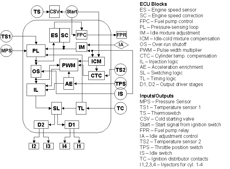
مخفف Electronic Control Unit يا واحد کنترل الکترونيک مي باشد و نقش هدايت و کنترل يک خودروي انژکتوري را بر عهده دارد. همانطور که مي دانيد خودروهاي انژکتوري بدليل عملکرد بهتر و توانايي پاس کردن استانداردهاي آلودگي، بطور کامل در تمام دنيا جايگزين خودروهاي کاربراتوري شده اند و مغز اين سيستم ECU مي باشد. ECU با توجه به سنسورهايي که به موتور متصل است وضعيت و شرايط خودرو را تحليل کرده و پاسخهاي لازم را به خروجيها که عبارتند از: انژکتورها، جرقه زنها و ... اعمال مي کند. سنسورهاي کيت هاي انژکتوري مختلف هستند که هر چه تعداد آنها بيشتر باشد ECU بهتر مي تواند شرايط موتور را درک کند. سنسورهاي مهم خودروهاي انژکتوري عبارتند از: سنسور دور يا RPM، سنسور فشار داخل مانيفولد يا MAP، سنسور دريچه گاز يا TPS، سنسور دماي آب يا CTS، سنسور دماي هوا ATS، سنسور اکسيژن يا لاندا، سنسور ضربه و ...
سازندگان معروف ECU چه شرکتهايي هستند؟
1) شرکت Bosch آلمان: اين شرکت بهترين و معروفترين سازنده ECU و کيت انژکتوري در دنيا مي باشد و در اغلب خودروهاي پيشرفته جهان نشاني از آن را مي توان يافت. چند مدل از زانتيا موجود در ايران داراي کيت انژکتوري Bosch مي باشد.
۲) شرکت Delco آمريکا: اين شرکت يکي از قديمي ترين شرکتهاي سازنده ECU مي باشد و ECU آن در اغلب خودروهاي آمريکايي بخصوص خودروهاي شرکت GM يا جنرال موتورز بکار رفته است مانند کاديلاک، پونتياک و... همچنين در خودروهاي دوو کره مانند دوو ESPERO.
۳) شرکت Ford آمريکا: اين شرکت سازنده خودرو، سازنده ECU البته براي خودروهاي فورد مي باشد و اولين بار ايده کنترل تطبيقي يا خود-يادگير در خودروهاي اين شرکت عملا پياده سازي شد.
۴) شرکت Siemens آلمان: فعاليت اين شرکت گرچه به اندازه رقيب آلماني آن يعني Bosch نيست اما ECU هاي خوبي مي سازد. ECU پرايد انژکتوري موجود در ايران طراحي اين شرکت است.
۵) شرکت Magneti Marelli ايتاليا: اين شرکت در اروپا محبوبيت زيادي داشته و بر روي اغلب خودروهاي اروپايي کيت آن نصب است. به عنوان مثال خودروهاي فيات مدل PUNTO و فولکس واگن مدل GOLF IV، مزدا ۳۲۳.
۶) شرکت Sagem فرانسه: بر روي اغلب ماشينهاي فرانسوي ECU اين شرکت نصب است. بنابراين پژو ۲۰۶، مدلهايي از زانتيا؛ همچنين خودروهاي ايراني مانند سمند و پيکان انژکتوري.
۷) شرکت Nippon Denso ژاپن: اين شرکت توسط شرکت تويوتا تاسيس شده و بخش عمده سهام آن را دارا مي باشد البته ۶ درصد سهام آن متعلق به شرکت Bosch است. ECU اغلب خودروهاي تويوتا (مانند تويوتا لندکروز ) و برخي خودروهاي ژاپني مانند نيسان، هوندا، سوزوکي و ... متعلق به اين شرکت مي باشد.
شرکتهاي ديگري هم هستند مانند HITACHI، MATSUHITA، LOTUS و ...

UNICHIP يا فن آوري تنظيم ECU
امروزه موتورهاي انژكتوري نقشي بسيار اساسي در موفقيت صنايع خودروسازي ايفاء مينمايند و كيفيت و قابليتهاي آن، درصد كارايي خودرو را نشان ميدهد. همانطور كه ميدانيم كنترل كننده موتورهاي انژكتوري، بردي الكترونيكي به نام ECU ميباشد و در واقع كارايي اين بخش تعيين كننده كيفيت يك موتور و در ابعادي ديگر كيفيت خودرو خواهد بود؛ بدين معني كه هرچقدر ECU يك موتور بهتر طراحي شده باشد، آن موتور كيفيت بهتري خواهد داشت.
ECU بر اساس سنسورهايي كه بدان متصل است شرايط كار موتور را درك كرده و فرامين مناسب را به انژكتورها و شمعها صادر ميكند. از آنجا كه ديناميك خودرو بسيار پيچيده و غير خطي ميباشد، طراحان ECU براي سهولت كار، جداولي را به نام map داخل حافظه ECU ميريزند كه در آن مقدار پاشش سوخت و زاويه آوانس در هر دور و بار موتور مشخص شده است. هر چه دقت اين جداول بيشتر باشد، دقت عملكرد ECU بيشتر خواهد بود.
نكتهاي كه بايد توجه كرد اينست كه مقادير اين جدولها وابستگي مستقيمي به پارامترهاي جغرافيايي موتور، نظير فشار و دماي هوا دارد. شركتهاي خودروسازي، ECU را براي يك آب و هواي خاص طراحي نميكنند بلكه مقادير map را بگونهاي تنظيم ميكنند كه براي انواع شرايط جغرافيايي جوابي بهينه و معقول بدهد. بنابراين map، در اين حالت براي تمام خودروهاي از يك مدل بهينه است نه هر خودروي خاص؛ زيرا هيچ دو خودرويي، حتي از يك مدل كاملاً مانند يكديگر نيستند.
اگر سيستمي بتواند اين نقيصه را از ECUها برطرف كند، آنگاه ميتوان به طور اختصاصي map هر خودرو را كاليبره كرده و توان آن را افزايش داد.
امروزه تيونينگ ECU خودروها، بحث جا افتاده اي است و شرکتهاي بسياري در اين زمينه فعاليت مي کنند بطور کلي دو روش براي تيونينگ خودروهاي انژکتوري وجود دارد. روش اول خواندن ديتاهاي (map) ECU و دادن ديتاهاي جديد که شرکتهاي بسياري در اين زمينه فعالند از جمله: Eurochip، Chip Tuning، Tech TV، Autospeed و ...يکي از اشکالات اين روش اينست که بشدت وابسته به ساختار ECU است و با پيچيده شدن سخت افزار ECU امکان خواندن و تغيير ديتاهاي آن مشکل و گاهي غيرممکن مي شود مگر آنکه شرکت سازنده ECU خود نحوه دسترسي به اطلاعات را در اختيار شرکتهاي تيونينگ بگذارد. روش دوم اضافه کردن يک سخت افزار جانبي به ECU جهت تغيير پارامترهاي ECU است. اين روش گرچه گرانتر تمام مي شود اما وابسته به نوع ECU نيست. يکي از شرکتهايي که در اين زمينه فعال است
، شرکت Dastek است. شرکتي که در آفريقاي جنوبي قرار دارد و با پرسنلي در حدود 30 نفر توانسته موفقِِِِت چشمگيري داشته باشد.جالب است بدانيد که اين شرکت بظاهر کوچک توانسته است محصول خود را به کشورهاي مختلف دنيا صادر کند و بيش از 300 نمايندگي فروش در سرتاسر دنيا دارد كه فقط 100 تا از آنها در ايالات متحده آمريكا هستند. نام اين محصول UNICHIP است.
اصول عملکرد UNICHIP بدين صورت كه سنسورهاي اصلي در يك موتور انژكتوري (MAP, RPM) را خوانده و سپس با توجه به نقطه كار موتور، مقاديري مجازي از اين دو سنسور را به ECU اعمال ميكند؛ بگونهاي كه رفتار ECU نسبت به حالت قبل بهبود پيدا ميكند.
آمارها نشان ميدهد كه موفقيت UNICHIP در اين زمينه بسيار بالا بوده است:از هر 400 خودرو، فقط يك خودرو ممكن است با UNICHIP بهينه نگردد، 80% خودروهايي كه در آفريقاي جنوبي استفاده ميشوند، UNICHIP را در خودروهاي خود نصب كردهاند، UNICHIP بر روي بيش از 320 مدل موتور از خودروسازان بزرگ دنيا پياده شده است.
+ نوشته شده در شنبه یکم اردیبهشت ۱۳۸۶ ساعت 11:44 توسط راشد جعفری
|
+ نوشته شده در شنبه یکم اردیبهشت ۱۳۸۶ ساعت 11:27 توسط راشد جعفری
|
| خودروی هیبریدی چگونه کار می کند؟ |
| |
مقدمه
امروزه با توجه به آلودگيهاي ناشي از خودروها و محدوديتهاي سوخت فسيلي، كارخانههاي خودروسازي گام مهمي در مقابله با اين امر برداشتهاند كه از جمله آنها می توان به خودروهاي هيبریدي (Hybrid Vehicle)، تکنولوژی پيل سوختي (Fuel Cell)، موتورهای با پاشش مستقيم بنزيني (GDI)، موتورهاي HCCI و خودروهاي دو گانه سوز (Bifuel) اشاره کرد.
بازدة بالا، آلايندگي كم، مسافت قابل پيمايش بالا، ايمني مطلوب و قيمت قابل رقابت با خودروهاي متداول از جمله ويژگيهاي حائز اهميت براي خودروهاي هيبريدي است. بسياري از خودروسازان بزرگ مبادرت به توليد اين خودروها در سطحی گسترده نمودهاند. در اين قسمت به شماي كلي از نحوة عملکرد، حالتهاي كاركردي، مزايا، معايب و تقسيمبندي سيستمهاي مختلف خودروي هيبريدي خواهيم پرداخت.
تاريخچة خودروي هيبريدي
يك مهندس آمريكائي به نام H.Piper در 23 نوامبر 1905 يك ماشين هيبريدي ساخت كه قادر بود در طي 10 ثانيه تا 25 مايل شتاب بگيرد. موتور اين خودرو تركيبی از موتور بنزيني و موتور الكتريكي بود كه امروزه به عنوان موتور هيبريدي شناخته ميشود. Piper در سه سال و نيم بعد، اختراع خود را ثبت نمود؛ اما پيشرفت سريع موتورهای احتراق داخلی با قدرت و گشتاور بالا در آن دوره، همچنين قابليت استارت بدون هندل آنها و از همه مهمتر پايين بودن قيمت سوختهای فسيلی و مطرح نبودن آلودگی محيط زيست، سبب عدم توجه به اين نوع خودروها شد. در پي بحرانهاي نفتي سالهاي 1970 دوباره اين خودروها مورد توجه قرار گرفتند ولي تا سال 1990 که كار اصولي با مشاركت PNGV (Partnership for a New Generation Vehicle) در آمريكا آغاز گرديد، این خودروها به طور جدی پيگيری نشدند.
امروزه خودروهاي هيبريدي مورد توجه كمپانيهاي بزرگ جهان قرار گرفته اند كه از آن جمله ميتوان به شركتهايي مانند: تويوتا، هندا، ميتسوبيشي، فورد، فيات، جنرال موتورز، دايملر كرايسلر، نيسان و پژو و ... اشاره نمود. توفيق اين محصولات به حدي چشمگير بوده كه از دسامبر سال 1997 تا ابتداي سال 2000 بيش از چهل هزار محصول پريوس كمپاني تويوتا به فروش رسيده است.
ويژگيها
خودروهاي هيبريدي، نوع تعميم يافته خودروهاي برقي خالص ميباشند كه معايب خودروهاي برقي خالص تا حدود زيادي در آنها برطرف گرديده است و مي توان گفت معايب خودروهاي احتراق داخلي نيز تا حدودي در آنها برطرف شده است. از مزاياي مهم اين خودروها نسبت به خودروهاي احتراق داخلي، كاركرد در دور و بار ثابت بوده و به اصطلاح در نقطة بهينة خود كار ميكنند كه اين امر باعث بالا رفتن بازده موتور و كاهش آلودگي و پايين آمدن مصرف سوخت ميگردد و ديگر اينكه به هنگام ترمزگيري و يا شتاب منفي، انرژي به صورت الكتريكي در باطری ها ذخيره ميشود و همين امر باعث كاركرد كمتر موتور احتراقي خواهد شد و در نتيجه منجر به كاهش آلودگي و پايين آمدن مصرف سوخت ميگردد. به عنوان مثال تويوتا پريوس (Toyota Prius) با موتور ۴ سيلندر ۱۵۰۰ سی سی مصرف سوختی معادل ۲/۴ ليتر در ۱۰۰ کيلومتر دارد. مزيت ديگر اين خودروها نسبت به خودروي برقي خالص، قابليت پيمودن مسيرهاي طولاني در هر بار شارژ كردن باطری ميباشد.
سيستمهاي ذخيره سازي انرژي :
خودروهای هيبريدی از ساختارهاي مختلفي برخوردارند. اما الزاما" يك خودروي هيبريدي از يك سيستم ذخير ساز انرژي، يك واحد توليد قدرت و يك سيستم انتقال قدرت تشكيل شده است. انتخابهاي اوليه براي سيستم ذخيره ساز انرژي باطريها، خازنها و فلايويلها هستند. اگر چه باطريها عمدهترين انتخاب در اين زمينه ميباشند اما تحقيق بر روي زمينههاي ديگر ذخيرهسازي انرژي آغاز شده است. باطری ها، بدلیل ارزان و تجاري بودن و نداشتن قسمتهاي متحرک اولين وسيله ذخيره انرژي و همانطور که گفته شد متداولترين است اما بزرگترین عیبشان عمر كوتاه آنها می باشد. البته باطريها با تكنولوژي جديد بسيار گران ميباشند و امروزه تعداد زيادي از باطريهاي جديد در حال توسعه هستند.
انواع خودروهاي هيبريدي :
با توجه به ساختار كنترلي و طريقه اتصال اجزاء به يكديگر، خودروهاي هيبريدي به سه نوع سري، موازي و سری-موازی تقسيمبندي ميشوند.
سيستم هيبريدي سري :
در اين دسته از خودروها موتور احتراق داخلي يك ژنراتور را ميچرخاند و اين ژنراتور، هم باطري را شارژ می كند و هم يك موتور الكتريكي را به حركت درميآورد و بدین صورت انتقال قدرت صورت می گيرد. در اين ساختار موتور احتراقي مستقيم به سيستم انتقال قدرت وصل نميشود.
اين سيستم به خاطر اين سري ناميده ميشود كه قدرت، به صورت سري به چرخها منتقل ميگردد و از آن براي رانش موتورهاي با قدرت كم و با رنج كاركرد بهينه استفاده می شود.
سيستم هيبريدي موازي :
در اين نوع سيستم، موتور احتراقي و موتور الكتريكي به صورت موازي چرخها را به حركت درميآورند. در اين سيستم موتور الكتريكي توسط باطري و موتور احتراقي توسط منبع سوخت فسيلي مستقيما" تغذيه ميگردند. در اين حالت ژنراتور حذف شده و باطري با تغيير حالت موتور الكتريكي به ژنراتور شارژ ميگردد. از آنجائيكه این سيستم فقط يك موتور دارد موتور الكتريكي نميتواند همزمان هم باطري را شارژ كند و هم باعث رانش چرخها گردد. يك تصوير ساده از اين سيستم در ذيل نشان داده شده است.
سيستم هيبريدي سري ـ موازي:
اين طرح بگونه ای است كه ميتوان از آن در شرايط مختلف به صورت هيبريد سري يا موازي استفاده نمود. در اين سيستم با بهرهگيري از فنآوري پيشرفته امكان استفاده از سيستم احتراقي و سيستم الكتريكي بطور جداگانه و همزمان وجود دارد. به اين ترتيب در مواقع شهري كاملا" الكتريكي و بدون آلودگي و در سرعتهاي بالا و در محدودة برون شهري ميتواند بطور مستقل احتراقي و يا تركيبي از دو سيستم باشد. در مواقعي چون شتابگيري سريع، هر دو سيستم با هم عمل ميكنند. چنين ايدهاي فقط بكمك يك فنآوري مدرن در يك خودرو سواري قابل اجراست. معمولا" چنين سيستمهايي از نوع تركيبي هستند و با بهرهگيري از يك استراتژي كنترلي مناسب عملا" همراه با فراهم آوردن عملكرد مناسب، سطح شارژ باطريها نيز در حد خوبی نگهداري ميشود بدين ترتيب اين خودرو ميتواند چه در شهر و چه در جاده به يك خودروي متداول تبديل گردد. در اين سيستم دو موتور الكتريكي وجود دارد كه بسته به شرايط ميتواند تركيبي از آنها به كار آيند و قابليت تبديل به ژنراتور را نيز دارند.
اين سيستم در خودرو Prius و Estima شرکت تويوتا استفاده شده است.
مقايسه چند نوع سيستم هيبريدي:
در شكل (1) مقايسهاي كلي از سه نوع سيستم هيبريدي صورت گرفته است كه در شكل (2) ميتوان مزايا و معايب سيستمها را در كنار هم مشاهده نمود.
با توجه به جدول فوق می توان خصوصیات زير را برای خودروهای هيبريد سری- موازی برشمرد:
۱- كاهش اتلاف انرژي: سيستم بطور اتوماتيك در حالت idle (درجا) خاموش ميشود و بدين ترتيب از به هدر رفتن انرژي جلوگيری می شود.
۲- ذخيرهسازي و برگرداندن انرژي: انرژيي كه در هنگام شتاب منفي و ترمزگيري هدر ميرود را به انرژي الكتريكي تبديل نموده و از اتلاف آنها جلوگيري ميكند.
۳- كمك به كاركرد موتور احتراقي: موتور الكتريكي در زمان شتابگيري به كاركرد موتور احتراقي كمك ميكند.
۴- كاركرد با بازدهي بالا: اين سيستم با يک استراتژی کنترلی مناسب، بازدهی کلی خودرو را در تمام شرايط کاری در حالت بيشينه نگه می دارد؛ بدين صورت که موتور الکتريکی مانند يک جبران ساز در شرايطی که قدرت موتور احتراق داخلی کافی نيست وارد عمل می گردد و در مواقعی که قدرت موتور احتراق داخلی بيشتر از نياز خودرو است، انرژی مازاد در باطريها ذخيره می گردد.
حالتهاي عملكردي موتور هيبريدي سری-موازی:
حالتهاي عملكردي يك موتور هيبريدي سری-موازی را ميتوان به شش قسمت تقسيم نمود:
حالت روشن شدن و دورهاي پايين و متوسط:
در اين حالت موتور احتراقي كه بازدهي مناسبی ندارد كاملا" خاموش است و فقط موتور الكتريكي توان مورد نياز خودرو را تأمين مينمايد (A)
حركت در حالتهاي معمولي:
قدرت ناشي از موتور احتراقي توسط تقسيم كنندة قدرت (Power split device) به دو بخش تقسيم ميگردد قسمتي از قدرت آن به ژنراتور ميرود كه منجر به حركت در آوردن موتور الكتريكي ميگردد (B) و مابقي چرخها را مستقيما" به حركت درميآورد (C) قدرت موتورا حتراقي در اين مرحله در حداكثر بازدهي است.
شتابگيري سريع:
در حاليكه قدرت يكنواختي از مسيرهاي B و C به چرخها منتقل می گردد توان اضافي توسط باطري نيز جهت افزايش توان موتور الکتريکی (A) تامين می گردد.
شتاب كندشونده و يا ترمزگيري:
موتور با قدرت بالا به ژنراتور با قدرت بالايي تبديل ميگردد كه توسط چرخها به حركت درميآيد. در اين حالت انرژي جنبشي به انرژي مكانيكي تبديل شده و در باطري ذخيره ميگردد. (D)
شارژ شدن باطري:
براي اينكه باطريها هميشه در حد قابل قبولي انرژي داشته باشند. در حالت ضروري كه احتياج باشد توسط موتور احتراقي شارژ ميگردد.(E)
حالت استراحت:
موتور به حالت اتوماتيك خاموش ميگردد.
|
+ نوشته شده در چهارشنبه بیست و نهم فروردین ۱۳۸۶ ساعت 18:5 توسط راشد جعفری
|
the road not yet taken
To end our dependence on rapidly dwindling oil supplies, switching to hybrid vehicles and ethanol fuel from corn simply isn't enough.
in his State of the Union speech this past January, President George W. Bush declared, "It's in our vital interest to diversify America's energy supply." He then went on to outline what he called "ambitious goals": reducing gasoline consumption by 20 percent in 10 years, boosting use of gasoline alternatives to 35 billion gallons over the same period, and incrementally increasing automobile fuel efficiency standards.
One word that was barely uttered in the speech was hydrogen. It was just a few years ago that hydrogen promised to deliver the clean, fuel-efficient transportation system President Bush has called for. But as knowledgeable scientists and engineers have pointed out, hydrogen is not a fuel source, but merely an energy carrier that must be manufactured. And a "cradle-to-grave"—or, more accurately, a "well-to-wheel"—analysis clearly demonstrates one thing: There is no currently available pathway to produce hydrogen, store it, transport it as an energy carrier, and use it to generate heat or electricity as efficiently as using the heat or electric power from the primary energy source (fossil or nuclear fuels, or sunlight) directly.
Although the current electric grid will have to be strengthened as more electric power is needed, the cost of expanding the existing grid would be much less than building a new hydrogen distribution and storage system from scratch. The cost of building a hydrogen distribution system has been estimated by various sources as costing from 500 billion to one trillion dollars.
These facts are especially relevant to building a secure transportation system for the United States. The U.S. transportation system depends almost entirely on oil. Imports have risen steadily since 1973 as demand increased, and domestic supplies reached a peak and began to decrease. Today, more than 60 percent of the oil consumed in the U.S. is imported, and the dependence on foreign oil, much of it from countries hostile to the United States, is bound to increase. Moreover, oil demand in developing countries, especially China and India, is increasing rapidly just as worldwide production is beginning to approach its peak. Once the world oil peak is reached and oil production begins to drop, the cost of fuel will increase steeply. Unless demand can be curtailed and alternative fuels can be supplied from domestic sources soon, an unprecedented social and economic crisis is likely to ensue.
Replacing the petroleum-based transportation system is of the utmost importance. We have available today options that will enable the development of a transportation system that is more efficient, more secure, and has less negative impact on the environment than the one the United States has currently. Access to petroleum is a problem today. Giving it up will actually be a blessing.
Some energy economists have claimed that there will be no oil supply crisis: Thanks to the so-called magic of the market, as oil becomes more expensive, producers will have incentive to provide more of it. Unfortunately, geology is not subject to the market. Even if the amount of ultimately recoverable oil reserves were to increase from the Energy Information Agency's mean estimate of three trillion barrels to its maximum estimate of four trillion barrels, that only pushes back the peak of production by 11 years. No matter how many places we open up to exploration, production will peak in this generation.
 |
 |
| An electric car (top) or plug-in hybrid (above) gets power by plugging into the electrical grid (below). |
 |
Unconventional supplies of oil also won't provide relief any time soon. The vast oil-shale deposits in Colorado, Utah, and Wyoming have long been hailed as a future energy source. However, more than half a century of research has not found an economical and environmentally benign way to use oil shale. Therefore, we cannot bank on this resource to help us now. We must instead start to supplement oil as the primary transportation fuel because an orderly transition to develop petroleum substitutes will take time and careful planning.
For instance, turnover in the national automobile fleet is achingly slow. The number of cars that are retired each year, according to statistics compiled by the U.S. Government, can be approximated as a steady 5 percent over 20 years until none remain on the road. The number of new cars added each year can be approximated as 7 percent of the existing fleet. With these rates of turnover and assuming that suddenly all new cars were high-efficiency vehicles, after 10 years 41 percent of all vehicles on the road still would be from the initial low-efficiency fleet, and only after 20 years would essentially all vehicles be high-efficiency. Any realistic scenario would require much longer to convert the fleet to high-efficiency vehicles. To make a large difference in fleet fuel efficiency, then, changes need to be initiated immediately and must be substantial.
Hybrid electric vehicles like the ones on the road today are twice as fuel efficient as the current average vehicle. But the near-term reduction in fuel consumption of hybrid vehicles has been overstated. Even if starting tomorrow half of all new cars and trucks sold in the U.S. were hybrid electric—an absurd proposition—the annual fuel savings in 10 years' time would be less than 15 percent. Even after 20 years, the cumulative savings would be less than one-sixth of what would be otherwise consumed.
Therefore, we need to introduce technologies that use even less petroleum. One technology that can achieve this is the plug-in hybrid electric vehicle. A plug-in hybrid can run moderate distances drawing only on its stored electricity, like a pure electric vehicle, then switch on the engine to extend its range when the battery is drawn down.
The diesel engine is inherently 25 to 30 percent more efficient than the spark-ignition (Otto cycle) engine. Diesel engines are now much cleaner and quieter than they were in the past. In Europe, roughly half of all new vehicles sold are diesel-powered. Furthermore, diesel fuel is more readily produced from coal and biomass than is gasoline. The gasoline engine in hybrid and plug-in hybrid vehicles could just as well be diesel engines to further improve efficiency.
The ultimate gasoline savings that a plug-in hybrid can provide depends on the size of its on-board battery pack, and the driving profile of the vehicle. They can be designed with different all-electric ranges. A PHEV60, a plug-in hybrid electric vehicle that could travel 60 miles on batteries alone, would see a greater number of miles traveled per year in all-electric mode than a PHEV20, with an all-electric range of 20 miles.
According to a study by the Electric Power Research Institute in Palo Alto, Calif., about one-third of the annual mileage for a typical PHEV20 would be electric-powered (EPRI, Technical Report 1009299, May 2004). Given the excellent efficiency of all-electric drivetrains (more than 80 percent, according to recent EPRI data), plug-in hybrids can reach parity with conventional vehicles in terms of life-cycle costs if the price per kilowatt-hour of battery storage were to come down to $316 per kilowatt-hour for a PHEV20 with gasoline at $1.75 a gallon. We have calculated that parity can be reached at a battery cost of about $1,600 per kWh if gasoline costs $2.50 a gallon.
The assumptions made in the EPRI report are very conservative because plug-in hybrid electric vehicles and battery technology are developing rapidly. There are companies, such as Hybrid Prius Inc. and CalCars, that claim PHEV30s can achieve 100 mpg.
 |
| One way to obtain liquid fuel from coal is the Fischer-Tropsch process, in which a synthetic gas made from coal is catalyzed. The liquid is similar to petroleum-derived diesel. |
 |
Also important is that plug-in hybrid vehicle technology provides utilities with a new and sustainable market for off-peak electric power. According to EPRI, consumer demand for electric power peaks during the day, while more than 40 percent of U.S. generating capacity sits idle or operates at reduced loads overnight. Vehicles could be recharged during these off-peak hours by installing software in the cars that would initiate battery charging only when excess power is available. This arrangement would also even out electricity consumption. Moreover, since no new production facilities or infrastructure would be required, the cost of recharging plug-in hybrids during off-peak hours would be only the extra fuel and operation and maintenance, much less than average utility rates.
High-efficiency vehicles won't solve the gasoline consumption problem alone. Even if every new car from this point forward were a diesel plug-in hybrid or battery electric vehicle, it would take until 2025 at the earliest to achieve a cumulative reduction in gasoline consumption equal to half what an all-gasoline fleet would use. Demand-side solutions are critical, but what is needed is a new way to obtain automotive fuel.
Fortunately, there are options beyond petroleum. Coal, natural gas, and biomass can be transformed chemically into liquid fuels. In the United States, the conversion of coal to liquid fuel has received a great deal of attention of late. The governor of Montana, Brian Schweitzer, as well as senators from Pennsylvania and other political leaders have been promoting the idea as a means of achieving energy independence.
To make coal into a vehicle fuel, it must first be converted to a synthesis gas of hydrogen and carbon monoxide. The sulfur contained in the coal is converted to hydrogen sulfide gas and captured; metals are removed as slag. The gaseous product may then be reacted to one of several chemical products that can be used as vehicle fuel. A big advantage of most liquid fuels is that they can use existing distribution infrastructure with little change, although high concentrations of ethanol require different storage materials.
What's more, the gasification process lends itself to the capture and sequestration of carbon dioxide, with an overall efficiency penalty of about 2 percent. Between the capture of CO2 at the point of manufacture and the greater efficiency of the plug-in hybrid vehicles, such an integrated system could greatly reduce the nation's greenhouse gas emissions.
The most commonly cited method for turning synthetic gas into liquid fuel is the Fischer-Tropsch process, which was invented by German scientists early in the last century and is used today in South Africa by Sasol to make diesel fuel. The Fischer-Tropsch reaction results in a liquid fuel consisting of approximately 75 percent synthetic diesel and 25 percent naphtha that is used to make synthetic gasoline.
Today, Sasol Ltd., the world's largest maker of motor fuel from coal, produces 160,000 barrels per day in Secunda, South Africa. The 50-year-old plant provides 28 percent of South Africa's supplies of such fuels as diesel, gasoline, and kerosene. Several large liquid-fuel projects are in progress in the Middle East, starting with natural gas that is otherwise flared.
Ramping up production of synthetic fuel won't happen overnight. The estimated time of construction for a plant is four to five years, and the capital investment is large. For example, the capital cost of a coal-gasification Fischer-Tropsch synthesis plant with a capacity to produce 20,000 barrels of liquid fuel per day is estimated to be on the order of $1.2 billion. At present, the U.S. uses something on the order of 20 million barrels of liquid fuel each day.
Opponents of coal gasification claim that there will be excessive greenhouse gas pollution from the process. However, in the future, vehicle fuel-cycle emissions of carbon dioxide can be reduced below those of gasoline-only powered vehicles, by the use of plug-in hybrid electric vehicles and by sequestration of the carbon dioxide from the fuel production process. And coal is far from the only feedstock available for the process. Natural gas can be reacted with steam to make synthetic gas that can be processed in the same way as coal. Indeed, the gas-to-liquid technology is so well developed that four major projects, totaling more than 360,000 barrels a day in production, have been announced in the past two years, including a 32,000 barrel-a-day joint project between Sasol and Qatar Petroleum and a 34,000 barrel-a-day ChevronTexaco facility under construction in Nigeria.
Biomass can be gasified either alone or in combination with coal and converted to liquid fuels by the same process as gasified coal. It can also be pyrolyzed and then processed into vehicle fuels.
Before choosing the direction of synthetic fuels, however, it is important to look at the efficiency of the process. Energy is lost in the conversion of coal, natural gas, or biomass into a vehicle fuel, and the energy efficiency of these conversion processes is important in determining the overall efficiency from well (or mine or farm) to wheel of these alternative pathways.
Ethanol from corn is a rapidly growing vehicle fuel, due largely to a federal subsidy of approximately 50 cents per gallon to the producer. This makes ethanol about the same price per gallon as gasoline, though it is still higher per mile driven. Although there has been controversy about the energy efficiency of ethanol from corn, it has been amply demonstrated that ethanol as currently produced from corn contains 1.25 to 1.3 times more energy than the source energy (not including the solar input to the crop) required to produce it (Farrell, et al., Science, Vol. 311, 506-508, 27 January, 2006, and rael.berkeley.edu/ EBAMM/Farrell).
All fossil fuel-based energy sources produce less energy than is input; gasoline contains only about 0.9 times the energy of the petroleum used to produce it, making it one of the most efficiently produced of fossil fuels. Other issues associated with corn-based ethanol are that corn is part of the food-supply chain, and its use results in a rather small reduction in CO2 emissions. Ethanol from sugar cane, or from nonfood crops such as switch grass, has a much higher energy output per fossil input than corn, and causes a much larger reduction in CO2 emissions.
One thing that the experience of the past half-century should teach us is not to rely too heavily on one source of energy for our transportation system. Instead of replacing a petroleum-fueled, internal combustion-powered system with one based entirely on hydrogen or biomass or fuel cells, we should identify the best two or three or four combinations of fuel and vehicle. And we should begin to switch to these new technologies immediately. As we have shown, even a radical change will take time to have a noticeable effect.
Fortunately, there are already several vehicle and fuel technologies available that can help us. Plug-in hybrid electric vehicles, for one, combine the best of both electric vehicles and hybrid technologies. Like electric vehicles, plug-in hybrids can be fueled with electricity generated from domestic sources and produce fewer CO2 emissions than conventional spark-ignition vehicles do, because of their improved mileage. Like any hybrid, the plug-in variety can run on liquid fuel for acceptable driving range. Because of the reduced fuel
consumption, it may be possible to provide the fuel entirely from domestic sources in the future.
But to ensure that the transition to plug-in hybrids or to some other technology happens rapidly, policy changes must be made. We need a stiff tax on carbon fuels to encourage efficiency, and we need CAFE standards tough enough to prod manufacturers into selling diesel, hybrid, and plug-in hybrid vehicles. Federal programs could spur the development of vehicles with a greater reliance on electric drive and the commercialization of coal- and biomass-based diesel fuel.
There is also a need for immediate research into a number of other related technologies that will be needed in the coming decades. Most importantly, we need to develop processes to produce ethanol from cellulosic material at a reasonable cost and investigate photochemical and high-temperature solar thermal reactions that can produce fuels, including hydrogen. We need to improve the performance of electrical storage in batteries or ultracapacitors. And we must develop technologies that can capture and store carbon dioxide. It's vital that these technologies are available within a generation, when they will be needed to augment or replace parts of the new transportation system we've outlined.
President Bush's ultimate goal of increased energy security is laudable, but the proposals that he calls ambitious don't go far enough. The suggestions we have presented have a better chance to provide us not only with increased energy security, but also, eventually, with energy independence, and they may help reduce the long-term threat to the nation from climate change. We believe this new system will work—and will do so in a way that should not be disruptive. Indeed, doing nothing—allowing the nation's fuel supply and vehicle fleet to remain unchanged right up to the moment when petroleum production begins to decline—would be a catastrophe, one that could be avoided if we were to take action now.
This article is based largely on a paper by West and Kreith in the Journal of Energy Resource Technology (Vol. 128, Sept. 2006, pages 236-243).
Frank Kreith is professor emeritus of mechanical engineering and Ron West is professor emeritus of chemical engineering, both at the University of Colorado in Boulder. The authors have been investigating questions regarding future energy supply for the past six years.
+ نوشته شده در چهارشنبه بیست و نهم فروردین ۱۳۸۶ ساعت 17:47 توسط راشد جعفری
|
Fahrenheit 3,600
Everywhere you look, the gas turbine industry is running hot.
One of the basic rules of gas turbines is that the hotter the gas that enters the work-producing
turbine from the combustor, the greater the thermal efficiency and output. Still, there are limits.Turbine inlet temperatures in the gas path of modern high-performance jet engines usually don't exceed 3,000°F, while non-aviation gas turbines operate at 2,700°F or lower.
But 3,600°F? That temperature exceeds the melting point of iron and the boiling point of molten silver. And yet the turbine airfoils in the new F135 jet engine that powers the Joint Strike Fighter Lightning II are capable of operating at these extreme temperatures. The F135 gas turbine is the first production jet engine in this new 3,600°F class, designed to withstand these highest, record-breaking turbine inlet temperatures.
There have been, in fact, quite a few accomplishments in the gas turbine industry over the last year. GE put into operation a simple-cycle 100 MW turbine that runs at 46 percent efficiency. Pratt & Whitney ramped up production of engines for a new class of aircraft, the very light jet. And construction of the first pebble bed nuclear reactor, set to be built in South Africa, was placed on the schedule.
But 3,600°F? That's hot. The JSF engine represents a bold—and necessary—step forward. This 40,000-pound thrust engine will power all three variants of the JSF: an Air Force fighter that takes off conventionally, a carrier-based Navy jet, and a short takeoff/vertical landing aircraft for the Marines. The STOVL version is the first aircraft to be able to do the "Hat Trick"—take off in a short distance, go into supersonic flight, then hover and land vertically. These varied missions require a very high thrust-to-weight ratio, and thus high turbine inlet temperatures.
 |
The powerful engine for the new Joint Strike Fighter on
its test platform in Florida (above) will develop 40,000 lbs. of thrust. The jet engine will come in Navy, Marine, and Air Force versions (below). |
 |
Last December, at Pratt & Whitney's Middletown, Conn., plant, Ed Crow, retired senior vice president and head of engineering at Pratt, took a few of us from the University of Connecticut Mechanical Engineering Department to view a F135 engine disassembled after 600 to 800 hours of operation. The blades and vanes of the high turbine, clad with ceramic thermal barrier coatings, are made of single crystal superalloys, which soften and melt at temperatures between 2,200 and 2,600°F. (Single crystal alloys were the subject of an article, "Crown Jewels," in ME magazine in February 2006.) Turbine airfoils closest to the combustor operate in a gas stream that can exceed their superalloy melting point by 1,000°F.
 |
 |
So how do turbine airfoils survive running conditions in this 3,600°F class engine? The vanes and blades are cooled to maintain acceptable service temperatures, some eight-tenths to nine-tenths of their melting temperature. Each high-temperature turbine airfoil is formed from an elaborate investment casting to accommodate the intricate internal passages and surface hole patterns necessary to channel and direct cooling air (bled from the compressor) within and over external surfaces of the airfoil structure. An error in airfoil cooling hole location or in cooling air pressure ratios could cause airfoil gas path inhalation rather than film cooling exhalation, which at the JSF's high turbine gas path temperatures would induce airfoil expiration. The JSF turbine film cooling design is based on some 30 years of gas turbine industry film cooling research and development, and unequivocally pushes forward the state-of-the-art of turbine performance and durability.
The JSF engine is just one product in the $3.7 billion military gas turbine market, which includes jet engine production for the world's fighter aircraft—such as the F15, F16, F22, F35, and Typhoon—military cargo, transport, refueling, and special-purpose aircraft. And that's just a fraction of the total worldwide gas turbine market.
A Steep Climb
David Franus of Forecast International in Newton, Conn., has again this year provided me with values of gas turbine manufacturing production, based on FI's proprietary databases and computer models. FI's values of production of gas turbines are unique in that they are for both aviation and non-aviation, the two disparate parts of the industry, usually reported on separately in trade journals. Worldwide gas turbine production for 2006 amounted to $27.6 billion, up significantly from $22 billion in 2005, but still below the 10-year average of $28.5 billion.
The aviation portion, all for manned aircraft jet and turboprop engines, amounted to $18.5 billion, two-thirds of the 2005 total value of gas turbine production.
The value of gas turbine production for commercial aviation is three to four times that of military, $14.8 billion in 2006. There is a prediction of $16.9 billion in 2010 (a 14 percent increase). This upward trend reflects the growth of the airline industry, evidenced by increased passenger loads (especially for Asian travel) since 9/11 and SARS, and an increase in the number of new airlines. Sales of existing models of Boeing and Airbus aircraft, using a variety of General Electric, Pratt & Whitney, Rolls-Royce, and Snecma engines, are strong, and both airframe companies are developing new models. Boeing has the new subjumbo 787, designed to serve what the company sees as the future demand of air travel, as well as a "new" superjumbo 747-8 family. (The 747 is an incredibly long-lived product line. I remember working on the first JT9D 747 jet engines, back in the 1960s at Pratt & Whitney Aircraft.). Airbus is developing its trouble-plagued superjumbo A380.
The air cargo market is strong and orders for new jet engine-powered freighters are high. Jet engine demand is also strong in regional airline and business aircraft markets.
 |
| The Siemens SGT-8000H gas turbine, shown here in a cutaway diagram, is the world's largest, rated at 340 MW with an efficiency of 60 percent. |
A booming area for new jet engines is the very light jet, or "air taxi" market (the subject of the article "Very Light and Fast" in January). A VLJ twin-engine aircraft with a pilot and from five to eight passengers, could provide point-to-point, on-demand air taxi service to some of the 5,000 local airports in North America. For flights shorter than 500 miles, VLJ aircraft use could enable air travelers to circumvent the bottleneck created by airport security and could eliminate layovers caused by the existing hub-and-spoke airline system.
Eclipse Aviation, Honda Aircraft Co., Cessna Aircraft Co., Citation, Embraer, and Adam Aircraft have entered the VLJ market, and Eclipse reports orders for 2,500 of its jets. Pratt & Whitney Canada is in full production for several thousand of the VLJ engines, in the 1,000- to 3,000-pound thrust range. Other VLJ engine OEMs are Williams International and Honda/GE.
In contrast with the steadily climbing aircraft market, the value of production for non-aviation gas turbines shows a boom-and-bust quality, rising to a peak of nearly $26 billion in 2001 before dropping back to around $8 billion a few years later. That behavior is caused by the rapid growth in—and sometimes speculative nature of—the electric power market, during this recent era of piecemeal utility deregulation.
Non-aviation gas turbines consist of electrical power generation, mechanical drive (mostly used to drive natural gas pipeline compressors), and marine (Navy, cruise ships, and ferry propulsion). The largest segment of that market by far is electrical power generation, in simple cycle (gas turbine only), combined cycle (gas turbine with its exhaust producing steam for steam turbine generation), and cogeneration (gas turbine, with its exhaust producing steam for heat, as described, for instance, in "Campus Heat and Power," Dec. 2006).
Forecast International predicts significant growth in coming years in demand for gas turbine electrical power generation, rising from $8.6 billion in 2006 to a projected $13.5 billion in 2008, a 60 percent increase. Based on a small sample of OEMs that I interviewed at the big Power-Gen conference and exhibit in Orlando last December, I agree with FI's predictions. In particular, two U.S. OEMs said that the cogeneration market for gas turbines was much stronger in Europe than in the U.S. In the words of one OEM exhibitor, "The sales are strong in those countries that signed the [Kyoto] treaty." Such an observation would seem to be at odds with assertions made by U.S. officials that signing the Kyoto treaty on greenhouse gas emissions would put the U.S. at an economic disadvantage.
Cleaning Coal
In many countries, such as the United States, South Africa, and China, coal is the major energy source, and it is used to produce electricity in steam Rankine cycle plants. At the Sino-American Technology and Engineering Conference I attended in Beijing last October, Xu Kuangdi, the president of the Chinese Academy of Engineering, remarked that of every three power plants currently being built in the world, two were in China, where the major fuel is coal.
Companies and government have been launching projects to design and develop integrated gasification combined-
cycle power plants. These IGCC plants convert coal into syngas, a low calorific value gas composed of carbon monoxide and hydrogen; the syngas is then used as fuel for a gas turbine, whose exhaust provides heat to generate steam to run a steam turbine. Using the same fuel twice, in essence, a combined-cycle power plant can have thermal efficiencies as high as 60 percent. There are now only two IGCC plants in operation in the United States, compared with 1,100 pulverized coal steam power plants, all with thermal efficiencies much, much lower than 60 percent. If IGCCs prove to have reasonable capital costs per kilowatt, the market for gas turbines could be very promising.
The first standardized commercial IGCC plants are being built by GE Energy and Bechtel, for American Electric Power, the U.S.'s largest electrical generator. Also, the U.S. Department of Energy has initiated FutureGen, a program to build the first integrated sequestration and hydrogen production plant. This is to be a zero-emissions fossil fuel plant using, of course, gas turbines.
The very largest electric power gas turbines are identified as H class, a designation that has lightheartedly been interpreted as an abbreviation for "humongous" (see "A Year of Turbulence," ME magazine's Power & Energy, June 2004). A General Electric GE Energy 9H gas turbine weighs in at 405 tons (367,900 kg), and the first one went into natural gas fuel operation at Baglan Bay, Wales, in 2003. In combined-cycle operation this unit can input 520 MW into the U.K.'s electric power grid, at a plant thermal efficiency of just under 60 percent.
Siemens' first H class gas turbine combined-cycle plant is now under construction in Irsching, Germany. It's also slated to have a thermal efficiency over 60 percent, and a plant output of 530 MW. The Siemens SGT-8000H gas turbine itself is rated at 340 MW, making it the world's largest.
The two companies differ in their design philosophy on turbine cooling systems. GE Energy H units are steam cooled—closely tying together the steam (Rankine) and gas turbine (Brayton) cycles—while the Siemens H gas turbine will be cooled by air bled from the compressor.
 |
| Wild animals graze along the road to the Koeberg nuclear power station (below). The site, home to a 1,800 MW conventional nuclear power station, will see construction of the world's first pebble bed nuclear reactor in 2008. The new reactor will have an output of 165 MW. |
 |
While H machines are designed mainly for base load electric power markets, General Electric's new LMS100 gas turbine is aimed at the mid-merit and daily cycling segments—the difficult-to-predict, must-be-ready-to-start electric peak power providers. The LMS100 is rated at 100 MW and, at 46 percent, has the highest efficiency of any simple cycle gas turbine. It is the first modern production electric power gas turbine that has an intercooler. This is a water-cooled, shell-and-tube heat exchanger through which gas path flow between the high and low compressor is cooled, making for less compressor work. The resulting heated intercooler water can then be used for some other purposes, but more importantly, the net gas turbine output is increased and colder turbine cooling air is made available, boosting thermal efficiency.
The LMS100 is an aeroderivative, based on GE's CF6-80C1 jet engine, but perhaps should be called a hybrid aeroderivative since the machine's low compressor is derived from GE's heavy-frame MS6001FA gas turbine. The first production unit of this innovative, intercooled gas turbine went into operation at Groton, S.D., last year.
This past February, while in Cape Town, South Africa, I visited what will be the site of the world's first nuclear-powered gas turbine electric power plant. The consortium Pebble Bed Modular Reactor (Pty) Ltd. will begin construction by May 2008, and Westinghouse of the U.S., Mitsubishi Heavy Industries of Japan, Nukem of Germany, and South Africa's utility, Eskom, are all participating.
This first PBMR unit will have an output of 165 MW provided by a closed-cycle gas turbine designed and developed by Mitsubishi and operating with helium gas. The helium is heated in a nuclear graphite-modulated, high-temperature reactor, approximately 88 feet high and 20 feet in diameter. The reactor is filled with 450,000 fuel "pebbles," managed in such a way that the reactor need not be shut down for refueling. Each 6 cm diameter graphite pebble (about the size of a tennis ball) is heated by nuclear reactions going on in some 15,000 kernels of uranium dioxide, each about 0.5 mm diameter, dispersed in the pebble, and individually encased in protective layers of carbon and silicon carbide.
The helium enters the pebble bed at 500°C and 9 Mpa, and is heated to about 900°C before it enters the turbine, then on to a recuperator, compressor, intercooler, recuperator, and then back into the pebble bed reactor, thus producing a nuclear-heated, Brayton thermodynamic closed cycle. In a closed-cycle operation, electric load variation is accomplished by varying the amount of helium in the system (A book on the subject, Closed-Cycle Gas Turbines, by Hans Frutschi is available from ASME Press). The PBMR is designed to have a relatively high thermal efficiency: 41 percent, compared to 33 percent for a conventional light water reactor using a Rankine cycle.
One selling point of the design is that any loss of coolant will shut down the nuclear reactions. This first PBMR unit, in fact, will be built right next to Eskom's Koeberg 1,800 MW Rankine cycle nuclear power plant. That facility is located on 7,500 acres of the Koeberg Nature Reserve, on the Atlantic coast less than 20 miles north of Cape Town. It's a very picturesque location for a generating station of any sort, and probably the only nuclear power plant in the world patrolled by wild springboks and zebras.
Lee S. Langston is professor emeritus of mechanical engineering at the University of Connecticut in Storrs. A frequent contributor to Mechanical Engineering, he is the former editor of ASME's Journal of Engineering for Gas Turbines and Power.
+ نوشته شده در چهارشنبه بیست و نهم فروردین ۱۳۸۶ ساعت 13:32 توسط راشد جعفری
|
|
پيل سوختي
اولين پيل سوختي توسط سر ويليام گرو در سال 1839 توسعه يافت، ولي تا مدتها از آن استفاده عملي نشد، تا اينكه در سال 1960، ناسا اين فنآوري را براي توليد الكتريسيته بر روي فضاپيماهاي آپولو و جميني نصب كرد. پيلهاي سوختي در مقايسه با سيستمهاي توليد توان متداول، مزاياي بسياري دارند؛ بازده الكتريكي نسبتاً بالاتر، ميزان انتشار آلايندههاي كم، انعطاف پذيري در مورد محل نصب، قابليت اطمينان بالا، ملزومات و هزينه تعمير و نگهداري كم، كارآيي part-load فوق العاده، تعديل پذير بودن و قابليت بكارگيري سوختهاي مختلف. به خاطر بازده و مزاياي زيست محيطيشان، فنآوري پيل سوختي يك راه حل بسيار جذاب و مفيد در قرن بيست و يكم براي رفع مشكلات انرژي خواهد بود.
فرايند الكتروشيميايي در پيل سوختي
پيل سوختي (FC) فنآوري است كه بدون داشتن اجزاي متحرك، انرژي شيميايي را به انرژي الكتريكي تبديل ميكند. پيل سوختي نيز مانند باتريها، بر اساس اصول الكترو شيميايي كار ميكند. يك پيل سوختي شامل دو الكترود (آند و كاتد) است كه به وسيله يك ماده الكتروليت از هم جدا شدهاند. بخشي از يك پيل سوختي كه شامل الكترودها و مواد الكتروليت است، «استك» ناميده ميشود و بطور كلي بخش هزينهبَر آن محسوب ميشود. با وجود اينكه پيلهاي سوختي از نظر مواد الكتروليتي متفاوتند، ولي همه آنها با اصول پايه يكساني كار ميكنند. |
|
|
.png)
|
|
شكل1 فرايند الكتروشيميايي در پيل سوختي |
|
پيلهاي سوختي را از نظر نوع الكتروليت بكار رفته در آن تقسيم بندي ميكنند. در حال حاضر پنج نوع پيل سوختي وجود دارد: پيلهاي سوختي آلكالين (AFC)، پيلهاي سوختي اسيد فسفريك (PAFC)، پيلهاي سوختي پليمري (PEFC) (در بعضي مراجع از آن به پيلهاي سوختي غشاء تبادل پروتون (PEMFC) ياد شده است)، پيلهاي سوختي كربنات مذاب (MCFC) و پيلهاي سوختي اكسيد جامد (SOFC).
سوخت اين پيلها هيدروژن است. هيدروژن را هم ميتوان به صورت مستقيم بكاربرد، و هم ميتوان آن را از منابعي كه از لحاظ هيدروژن غني هستند، استخراج كرده و سپس به مصرف رساند. اين منابع عموماً هيدروكربنهايي نظير بنزين، پروپان، متانول، گاز طبيعي و غيره هستند. براي استخراج هيدروژن از اين منابع به يك دستگاه جانبي بنام مبدل (reformer) كه پيش از ورود سوخت به پيل قرار ميگيرد، نياز است.
روش كار به اين صورت است كه، سوخت هيدروژن به آند پيل سوختي تغذيه شده و اكسيژن (يا هوا) نيز از طريق كاتد وارد پيل سوختي ميشوند. به كمك يك كاتاليست اتمهاي هيدروژن به يونهاي مثبت و منفي تبديل ميشوند. يونهاي مثبت كه حاوي پروتونها (H+) هستند از ميان الكتروليت عبور كرده و به سمت كاتد ميروند، ولي يونهاي منفي (الكترونها) نميتوانند از الكتروليت عبور كنند. به همين خاطر الكترونها از يك مدار خارجي عبور داده ميشوند. در ضمن عبور الكترونها از اين مدار خارجي، الكتريسيته توليد ميشود و سرانجام الكترونها به كاتد ميرسند. در كاتد يونهاي مثبت و منفي در مجاورت يك اكسيد كننده (اكسيژن يا هوا) با هم دوباره تركيب شده و با اكسيژن موجود تشكيل آب و گرما ميدهند.
كاربرد پيل سوختي در توليد همزمان
استفاده از محتواي انرژي گرمايي حاصله از واكنش الكتروشيميايي پيل سوختي، باعث ميشود كه بازده اينگونه سيستمها به مقدار قابل ملاحظهاي بهبود يابد. عموماً گرما به شكل آب داغ يا بخار فشار پايين (كمتر از 30psig ) بازيافت ميشود، ولي كيفيت گرماي حاصله به نوع پيل سوختي و دماي كاري آنها بستگي دارد (جدول1). در بين انواع پيل سوختي پايينترين كيفيت دمايي را پيلهاي نوع PEFC، با دماي كاري بين 65 تا 85 درجه سانتيگراد دارند. همانطور كه مشاهده ميشود پيلهاي سوختي نوع SOFC و MCFC با گستره دمايي بين 650 تا 1000 درجه سانتيگراد، در كاربردهاي CHP كه نياز به توليد بخار فشار بالا و متوسط است، بسيار مناسب ميباشند. بطور كلي گرماي بازيافت شده از سيستمهاي CHP پيل سوختي، براي گرمايش فضاي ساختمانها، گرمايش آب آشاميدني و فرآيندهايي كه نياز به دماهاي پايين و متوسط دارند، مناسب ميباشد. |
|
جدول1 دماي كاري و بازده انواع پيل سوختي
|
نوع پيل سوختي |
بازده الكتريكي |
بازده به صورت CHP |
دماي كاري (C°) |
|
آلكالين (AFC) |
32%-40% |
NA |
90-260 |
|
اسيد فسفريك (PAFC) |
35%-45% |
75% |
190-210 |
|
پليمري (PEFC) |
25%-35% |
72% |
65-85 |
|
كربنات مذاب (MCFC) |
40%-50% |
70% |
650-700 |
|
اكسيد جامد (SOFC) |
45%-55% |
70% |
750-1000 | |
+ نوشته شده در چهارشنبه بیست و نهم فروردین ۱۳۸۶ ساعت 13:10 توسط راشد جعفری
|
|
 Since
its inception in the 1940s, finite element analysis—originally
developed for numerical solution of complex problems in structural
mechanics—has become established in nearly all engineering fields,
including bioengineering, where it plays a role in studying many parts
of the body, such as nasal passages.
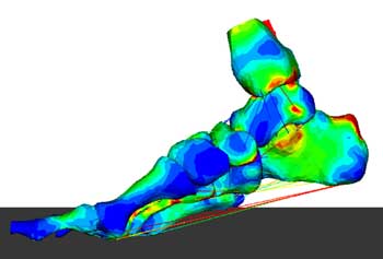
Since
its inception in the 1940s, finite element analysis—originally
developed for numerical solution of complex problems in structural
mechanics—has become established in nearly all engineering fields,
including bioengineering, where it plays a role in studying many parts
of the body, such as nasal passages.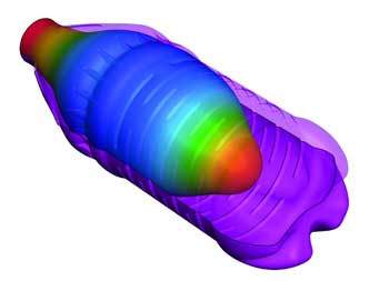
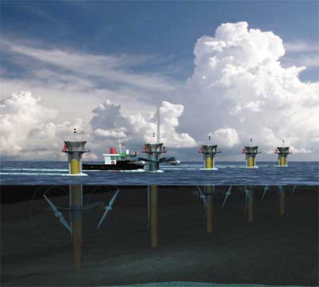 A conception of a field of water mills designed by Marine Current Turbines that turn the currents of tides into electricity.
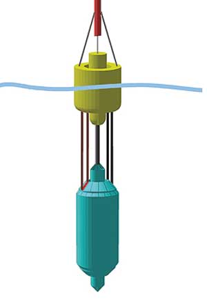 The WaveBob generates power by using the out-of-phase heaving motions of the float and a submerged inertial body.
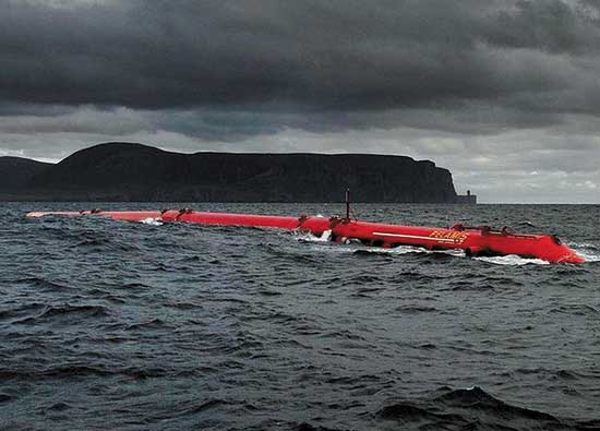 The Pelamis wave-power electricity generator has a closed hydraulic system inside its articulated components.




 با سلام,